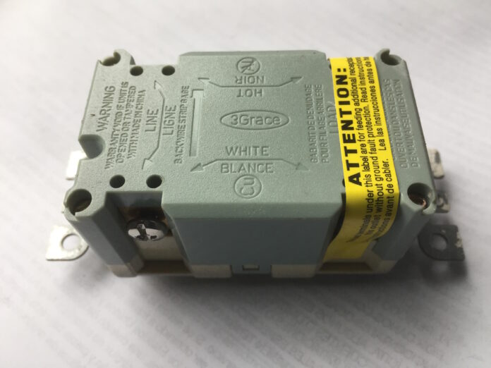
There is an ongoing discussion on the best way to connect the cables in the surface transmission system, or GFCI, outlets. This is done so that the two sets of depots the Power lines and the LOAD endpoints, can be distinguished by GFCIs. When you connect directly to the line terminals, the outlet only provides GFCI security. When you attach to the line and the load connections, the outlet protects itself, and all other outlets lower down on that different electrical circuit.
Establishment of Lines
The established minimum is the location of the connection of the external feeder wire, sometimes referred to as the line, which is supplied by the home’s electricity supply panel. The line connection is required for all GFCI outlet structures.
The circuit’s warm wire, often red or black, is linked to the black or bronze screwed connectors labeled LINE. The white grounding wire connects the titanium screw terminal with the designation LINE.
The different load marks are frequently printed on the bottom of the news outlet’s plastic material. The line ends aren’t concealed when you remove the outlet from the supplier’s packaging, making it simple to see them.
Load Attachment
When you extract the GFCI outlet from its box, the load terminals are frequently covered by a piece of tape (usually yellow). The load connector can supply additional ordinary outlets upstream first from GFCI to guard against it.
In other words, every standard outlet system from the GFCI’s electrical supply obtains ground-fault circuit prevention from the GFCI receptacle.
Benefits
The benefit of doing so is that it reduces costs because, when adding additional outlets to the exact circuits, you only need to purchase one GFCI as opposed to each individual outlet. GFCIs cost significantly more than standard outlets. The disadvantage is that when any of these extra outlets have a ground-fault condition, one GFCI outlet trips. If the equipment is far away, in that other structure, or outside, activating the GFCI & powering on those outlets could be a problem.
Requirement of load hookup
The load hookup requires two wires in the GFCI’s power box. The first is a cable that connects to the GFCI’s Load side. The other wire is attached to the Load side to provide power downwards to additional outlets and different configurations of variables. Like a collection, the loading network’s hot wire is linked to the news outlet’s black or gold terminal. The negatives wire is connected to the white terminal.
It is essential to remember that the GFCI primarily protects the outlets that appear downstream of an overload connection or farther away from the switchgear in terms of the circuit wiring when using the overload connection.
The other outlets are usually protected from that point on if the initial outlet on the circuit contains a GFCI. The GFCI does not provide coverage for any additional outlets between a different GFCI and the service committee.
Read More: Four Things You Must Look for AC Technician In Dubai.
Integrate with the Ground
The grounding screw of a GFCI is always sustained and is only ever located on one side of the socket body. This is where the uncoated or green neutral wire connects. Suppose the GFCI’s electrical box is aluminum. In that case, you must attach two ponytails (short lengths of wire) to the circuit’s neutral wire and another hairpin towards the plug bottom screw (not acrylic).
If the connection wiring is unplugged, the GFCI will still work as planned, but the socket won’t be grounded. GFCI safeguards are different from dropping protections.
How to Wire a GFCI Outlet: A Step-by-Step Guide
I’ll show you how to securely identify the different wires in your substation in this session, and then I’ll show you how to attach each one to a GFCI outlet.
We’ll guide you through every step of connecting the cables using my antennae mast as an illustration so that you can power this 15-amp GFCI outlet while also delivering power and GFCI protection to receptacles downstream.
Electrical wiring may initially seem a little frightening. Still, with the correct safety measures, some basic knowledge, and attention to detail, you can be connected safely and correctly from the beginning.
Are Ground Wires Required for GFCIs?
Before we test and hook up our GFCI, let’s talk quickly about ground wires.
One of the biggest misconceptions concerning GFCI circuits is that a ground wire is necessary. Although it is recommended, grounding is not required for certain GFCI to work correctly.
A breakdown of terminated connections for GFCI outlets
White neutral wires are attached to the silver completing of a GFCI outlet, while black burning wires are connected to the palladium (brass) terminals. Black turns to gold, while white turns silver.
The wires carrying power into the box should be linked to the “line” connections, while the cables going to outlets downstairs should be attached to the “load” terminals.
The cables feeding the box with electricity:
- A black hot wire is terminated with a gold “line.”
- Termination of the white neutral conductor to the silver “line.”
- The cables leading to the downstream exit.
- Black hot wire to the gold “load” terminal.
- White neutrality wire to silver “load” terminal.
- To connect a GFCI outlet, the cables must be attached.
Installing the ground wire
It’s always a good idea to connect your ground if you have one. Syringe pliers will help tightly wrap the wiring around the item.
Repairing the outlet and reattaching the neutral & main wires
As stated in the chapter before under “Overview of both the Terminal Connections,” the hot & middle wires from my power box will now be linked to the GFCI’s terminal by inserting the ends into the set of numbers on each wire and fastening the screws with a hammering.


